
Crystal radio

A crystal radio receiver, also called a crystal set, is a simple radio receiver, popular in the early days of radio. It uses only the power of the received radio signal to produce sound, needing no external power. It is named for its most important component, a crystal detector, originally made from a piece of crystalline mineral such as galena.[1]: 7–9 This component is now called a diode.
Crystal radios are the simplest type of radio receiver[2] and can be made with a few inexpensive parts, such as a wire for an antenna, a coil of wire, a capacitor, a crystal detector, and earphones.[3] However they are passive receivers, while other radios use an amplifier powered by current from a battery or wall outlet to make the radio signal louder. Thus, crystal sets produce rather weak sound and must be listened to with sensitive earphones, and can receive stations only within a limited range of the transmitter.[4]
The rectifying property of a contact between a mineral and a metal was discovered in 1874 by Karl Ferdinand Braun.[5][6][7]: 333 Crystals were first used as a detector of radio waves in 1894 by Jagadish Chandra Bose,[8][7]: 291–308 in his microwave optics experiments. They were first used as a demodulator for radio communication reception in 1902 by G. W. Pickard.[9] Crystal radios were the first widely used type of radio receiver,[10] and the main type used during the wireless telegraphy era.[11] Sold and homemade by the millions, the inexpensive and reliable crystal radio was a major driving force in the introduction of radio to the public, contributing to the development of radio as an entertainment medium with the beginning of radio broadcasting around 1920.[12]
Around 1920, crystal sets were superseded by the first amplifying receivers, which used vacuum tubes. With this technological advance, crystal sets became obsolete for commercial use[10] but continued to be built by hobbyists, youth groups, and the Boy Scouts[13] mainly as a way of learning about the technology of radio. They are still sold as educational devices, and there are groups of enthusiasts devoted to their construction.[14][15][16][17][18]
Crystal radios receive amplitude modulated (AM) signals, although FM designs have been built.[19][20] They can be designed to receive almost any radio frequency band, but most receive the AM broadcast band.[21] A few receive shortwave bands, but strong signals are required. The first crystal sets received wireless telegraphy signals broadcast by spark-gap transmitters at frequencies as low as 20 kHz.[22]: 110,268 [23]
Basic principles
[edit]

A crystal radio can be thought of as a radio receiver reduced to its essentials.[3][24] It consists of at least these components:[21][22]: 94 [25][26]
- An antenna in which the radio wave induces electric currents.
- A resonant circuit (tuned circuit) which selects the frequency of the desired radio station from all the radio signals received by the antenna. The tuned circuit consists of a coil of wire (called an inductor) and a capacitor connected together. The circuit has a resonant frequency, and allows radio waves at that frequency to pass through to the detector while largely blocking waves at other frequencies. One or both of the coil or capacitor is adjustable, allowing the circuit to be tuned to different frequencies to select the station to receive. In some circuits a capacitor is not used and the antenna serves this function, as an antenna that is shorter than a quarter-wavelength of the radio waves it is meant to receive is capacitive.
- A semiconductor crystal detector that demodulates the radio signal to extract the audio signal (modulation). The crystal detector functions as a square law detector,[27] demodulating the radio frequency alternating current to its audio frequency modulation. The detector's audio frequency output is converted to sound by the earphone. Early sets used a "cat whisker detector"[28][29][30] consisting of a small piece of crystalline mineral such as galena with a fine wire touching its surface. The crystal detector was the component that gave crystal radios their name. Modern sets use modern semiconductor diodes, although some hobbyists still experiment with crystal or other detectors.
- An earphone to convert the audio signal to sound waves so they can be heard. The low power produced by a crystal receiver is insufficient to power a loudspeaker, hence earphones are used.

As a crystal radio has no power supply, the sound power produced by the earphone comes solely from the transmitter of the radio station being received, via the radio waves captured by the antenna.[3] The power available to a receiving antenna decreases with the square of its distance from the radio transmitter.[31] Even for a powerful commercial broadcasting station, if it is more than a few miles from the receiver the power received by the antenna is very small, typically measured in microwatts or nanowatts.[3] In modern crystal sets, signals as weak as 50 picowatts at the antenna can be heard.[32]: 42 Crystal radios can receive such weak signals without using amplification only due to the great sensitivity of human hearing,[3][33]: 297–304 which can detect sounds with an intensity of only 10−16 W/cm2.[34] Therefore, crystal receivers have to be designed to convert the energy from the radio waves into sound waves as efficiently as possible. Even so, they are usually only able to receive stations within distances of about 25 miles for AM broadcast stations,[22]: 144 [35] although the radiotelegraphy signals used during the wireless telegraphy era could be received at hundreds of miles,[35] and crystal receivers were even used for transoceanic communication during that period.[36]
Design
[edit]Commercial passive receiver development was abandoned with the advent of reliable vacuum tubes around 1920, and subsequent crystal radio research was primarily done by radio amateurs and hobbyists.[37] Many different circuits have been used.[2][38][39] The following sections discuss the parts of a crystal radio in greater detail.
Antenna
[edit]
The antenna converts the energy in the electromagnetic radio waves to an alternating electric current in the antenna, which is connected to the tuning coil. Since, in a crystal radio, all the power comes from the antenna, it is important that the antenna collect as much power from the radio wave as possible. The larger an antenna, the more power it can intercept. Antennas of the type commonly used with crystal sets are most effective when their length is close to a multiple of a quarter-wavelength of the radio waves they are receiving. Since the length of the waves used with crystal radios is very long (AM broadcast band waves are 182–566 metres or 597–1,857 feet long)[40] the antenna is made as long as possible,[41] from a long wire, in contrast to the whip antennas or ferrite loopstick antennas used in modern radios.
Serious crystal radio hobbyists use "inverted L" and "T" type antennas,[42]: 48–51 consisting of hundreds of feet of wire suspended as high as possible between buildings or trees, with a feed wire attached in the center or at one end leading down to the receiver.[43][21]: 58 However, more often, random lengths of wire dangling out windows are used. A popular practice in early days (particularly among apartment dwellers) was to use existing large metal objects, such as bedsprings,[13] fire escapes, and barbed wire fences as antennas.[35][44][22]: 100
Ground
[edit]The wire antennas used with crystal receivers are monopole antennas which develop their output voltage with respect to ground. The receiver thus requires a connection to ground (the earth) as a return circuit for the current. The ground wire was attached to a radiator, water pipe, or a metal stake driven into the ground.[45]: 18-22 [22]: 102–104 [42]: 48–51 In early days if an adequate ground connection could not be made a counterpoise was sometimes used.[46]: 309–311 [47]: 45 A good ground is more important for crystal sets than it is for powered receivers, as crystal sets are designed to have a low input impedance needed to transfer power efficiently from the antenna. A low resistance ground connection (preferably below 25 Ω) is necessary because any resistance in the ground reduces available power from the antenna.[41] In contrast, modern receivers are voltage-driven devices, with high input impedance, hence little current flows in the antenna/ground circuit. Also, mains powered receivers are grounded adequately through their power cords, which are in turn attached to the earth through the building wiring.
Tuned circuit
[edit]
The tuned circuit, consisting of a coil and a capacitor connected together, acts as a resonator, similar to a tuning fork.[47]: 48 Electric charge, induced in the antenna by the radio waves, flows rapidly back and forth between the plates of the capacitor through the coil. The circuit has a high impedance at the desired radio signal's frequency, but a low impedance at all other frequencies.[48] Hence, signals at undesired frequencies pass through the tuned circuit to ground, while the desired frequency is instead passed on to the detector (diode) and stimulates the earpiece and is heard. The frequency of the station received is the resonant frequency f of the tuned circuit, determined by the capacitance C of the capacitor and the inductance L of the coil:[49]

The circuit can be adjusted to different frequencies by varying the inductance (L), the capacitance (C), or both, "tuning" the circuit to the frequencies of different radio stations.[1]: 7–9 In the lowest-cost sets, the inductor was made variable via a spring contact pressing against the windings that could slide along the coil, thereby introducing a larger or smaller number of turns of the coil into the circuit, varying the inductance. Alternatively, a variable capacitor is used to tune the circuit.[50] Some modern crystal sets use a ferrite core tuning coil, in which a ferrite magnetic core is moved into and out of the coil, thereby varying the inductance by changing the magnetic permeability (this eliminated the less reliable mechanical contact).[51]
The antenna is an integral part of the tuned circuit and its reactance contributes to determining the circuit's resonant frequency. Antennas usually act as a capacitance, as antennas shorter than a quarter-wavelength have capacitive reactance.[41] Many early crystal sets did not have a tuning capacitor,[46]: 421–425 and relied instead on the capacitance inherent in the wire antenna (in addition to significant parasitic capacitance in the coil[47]: 57 ) to form the tuned circuit with the coil.
The earliest crystal receivers did not have a tuned circuit at all, and just consisted of a crystal detector connected between the antenna and ground, with an earphone across it.[1]: 7–9 [46]: 421–422 Since this circuit lacked any frequency-selective elements besides the broad resonance of the antenna, it had little ability to reject unwanted stations, so all stations within a wide band of frequencies were heard in the earphone[37] (in practice the most powerful usually drowns out the others). It was used in the earliest days of radio, when only one or two stations were within a crystal set's limited range.
Impedance matching
[edit]

An important principle used in crystal radio design to transfer maximum power to the earphone is impedance matching.[37][52] The maximum power is transferred from one part of a circuit to another when the impedance of one circuit is the complex conjugate of that of the other; this implies that the two circuits should have equal resistance.[1]: 7–9 [53][54] However, in crystal sets, the impedance of the antenna-ground system (around 10–200 ohms[41]) is usually lower than the impedance of the receiver's tuned circuit (thousands of ohms at resonance),[55] and also varies depending on the quality of the ground attachment, length of the antenna, and the frequency to which the receiver is tuned.[32]: 42 Therefore, in improved receiver circuits, in order to match the antenna impedance to the receiver's impedance, the antenna was connected across only a portion of the tuning coil's turns.[49][46]: 422 This made the tuning coil act as an impedance matching transformer (in an autotransformer connection) in addition to providing the tuning function. The antenna's low resistance was increased (transformed) by a factor equal to the square of the turns ratio (the ratio of the number of turns the antenna was connected to, to the total number of turns of the coil), to match the resistance across the tuned circuit.[54] In the "two-slider" circuit, popular during the wireless era, both the antenna and the detector circuit were attached to the coil with sliding contacts, allowing (interactive)[50][56]: 133 adjustment of both the resonant frequency and the turns ratio.[43]: 94 [57]: 281 [45]: 23-25 Alternatively a multiposition switch was used to select taps on the coil. These controls were adjusted until the station sounded loudest in the earphone.

Problem of selectivity
[edit]One of the drawbacks of crystal sets is that they are vulnerable to interference from stations near in frequency to the desired station.[2][4][32]: 42 Often two or more stations are heard simultaneously. This is because the simple tuned circuit does not reject nearby signals well; it allows a wide band of frequencies to pass through, that is, it has a large bandwidth (low Q factor) compared to modern receivers, giving the receiver low selectivity.[4]
The crystal detector worsened the problem, because it has relatively low resistance, thus it "loaded" the tuned circuit, drawing significant current and thus damping the oscillations, reducing its Q factor so it allowed through a broader band of frequencies.[32]: 42 [58] In many circuits, the selectivity was improved by connecting the detector and earphone circuit to a tap across only a fraction of the coil's turns.[37][42]: 63 This reduced the impedance loading of the tuned circuit, as well as improving the impedance match with the detector.[37]
Inductive coupling
[edit]

In more sophisticated crystal receivers, the tuning coil is replaced with an adjustable air core antenna coupling transformer[1]: 7–9 [37] which improves the selectivity by a technique called loose coupling.[46]: 423–425 [45]: 23-25 [59] This consists of two magnetically coupled coils of wire, one (the primary) attached to the antenna and ground and the other (the secondary) attached to the rest of the circuit.[50] The current from the antenna creates an alternating magnetic field in the primary coil, which induced a current in the secondary coil which was then rectified and powered the earphone. Each of the coils functions as a tuned circuit; the primary coil resonated with the capacitance of the antenna (or sometimes another capacitor), and the secondary coil resonated with the tuning capacitor. Both the primary and secondary were tuned to the frequency of the station. The two circuits interacted to form a resonant transformer.
Reducing the coupling between the coils, by physically separating them so that less of the magnetic field of one intersects the other, reduces the mutual inductance, narrows the bandwidth, and results in much sharper, more selective tuning than that produced by a single tuned circuit.[46]: 424–425 [60] However, the looser coupling also reduced the power of the signal passed to the second circuit. The transformer was made with adjustable coupling, to allow the listener to experiment with various settings to gain the best reception.
One design common in early days, called a "loose coupler", consisted of a smaller secondary coil inside a larger primary coil.[37][43]: 96–101 The smaller coil was mounted on a rack so it could be slid linearly in or out of the larger coil. If radio interference was encountered, the smaller coil would be slid further out of the larger, loosening the coupling, narrowing the bandwidth, and thereby rejecting the interfering signal.
The antenna coupling transformer also functioned as an impedance matching transformer, that allowed a better match of the antenna impedance to the rest of the circuit.[42]: 64 One or both of the coils usually had several taps which could be selected with a switch, allowing adjustment of the number of turns of that transformer and hence the "turns ratio".
Coupling transformers were difficult to adjust, because the three adjustments, the tuning of the primary circuit, the tuning of the secondary circuit, and the coupling of the coils, were all interactive, and changing one affected the others.[61]
Crystal detector
[edit].jpg?lang=en)


The crystal detector demodulates the radio frequency signal, extracting the modulation (the audio signal which represents the sound waves) from the radio frequency carrier wave. In early receivers, a type of crystal detector often used was a "cat whisker detector".[29][63] The point of contact between the wire and the crystal acted as a semiconductor diode. The cat whisker detector constituted a crude Schottky diode that allowed current to flow better in one direction than in the opposite direction.[64][65] Modern crystal sets use modern semiconductor diodes.[58] The crystal functions as an envelope detector, rectifying the alternating current radio signal to a pulsing direct current, the peaks of which trace out the audio signal, so it can be converted to sound by the earphone, which is connected to the detector.[21][failed verification][62][failed verification] The rectified current from the detector has radio frequency pulses from the carrier frequency in it, which are blocked by the high inductive reactance and do not pass well through the coils of early date earphones. Hence, a small capacitor called a bypass capacitor is often placed across the earphone terminals; its low reactance at radio frequency bypasses these pulses around the earphone to ground.[57]: 282 In some sets the earphone cord had enough capacitance that this component could be omitted.[46]: 424
Only certain sites on the crystal surface functioned as rectifying junctions, and the device was very sensitive to the pressure of the crystal-wire contact, which could be disrupted by the slightest vibration.[6][47]: 60–61 Therefore, a usable contact point had to be found by trial and error before each use. The operator dragged the wire across the crystal surface until a radio station or "static" sounds were heard in the earphones.[22]: 143–146 Alternatively, some radios (circuit, right) used a battery-powered buzzer attached to the input circuit to adjust the detector.[22]: 143–146 The spark at the buzzer's electrical contacts served as a weak source of static, so when the detector began working, the buzzing could be heard in the earphones. The buzzer was then turned off, and the radio tuned to the desired station.
Galena (lead sulfide) was the most common crystal used,[45]: 23-25 [47]: 60–61 [66] but various other types of crystals were also used, the most common being iron pyrite (fool's gold, FeS2), silicon, molybdenite (MoS2), silicon carbide (carborundum, SiC), and a zincite-bornite (ZnO-Cu5FeS4) crystal-to-crystal junction trade-named Perikon.[67][57]: 311–318 Crystal radios have also been improvised from a variety of common objects, such as blue steel razor blades and lead pencils,[67][68] rusty needles,[9] and pennies[67] In these, a semiconducting layer of oxide or sulfide on the metal surface is usually responsible for the rectifying action.[67]
In modern sets, a semiconductor diode is used for the detector, which is much more reliable than a crystal detector and requires no adjustments.[67][58][69] Germanium diodes (or sometimes Schottky diodes) are used instead of silicon diodes, because their lower forward voltage drop (roughly 0.3 V compared to 0.6 V[70]) makes them more sensitive.[58][71]
All semiconductor detectors function rather inefficiently in crystal receivers, because the low voltage input to the detector is too low to result in much difference between forward better conduction direction, and the reverse weaker conduction. To improve the sensitivity of some of the early crystal detectors, such as silicon carbide, a small forward bias voltage was applied across the detector by a battery and potentiometer.[46]: 439 [72][73] The bias moves the diode's operating point higher on the detection curve producing more signal voltage at the expense of less signal current (higher impedance). There is a limit to the benefit that this produces, depending on the other impedances of the radio. This improved sensitivity was caused by moving the DC operating point to a more desirable voltage-current operating point (impedance) on the junction's I-V curve. The battery did not power the radio, but only provided the biasing voltage which required little power.
Earphones
[edit]
The requirements for earphones used in crystal sets are different from earphones used with modern audio equipment. They have to be efficient at converting the electrical signal energy to sound waves, while most modern earphones sacrifice efficiency in order to gain high fidelity reproduction of the sound.[3]: 93-94 In early homebuilt sets, the earphones were the most costly component.[22]: 285

The early earphones used with wireless-era crystal sets had moving iron drivers that worked in a way similar to the horn loudspeakers of the period. Each earpiece contained a permanent magnet about which was a coil of wire which formed a second electromagnet.[42]: 79 Both magnetic poles were close to a steel diaphragm of the speaker. When the audio signal from the radio was passed through the electromagnet's windings, current was caused to flow in the coil which created a varying magnetic field that augmented or diminished that due to the permanent magnet. This varied the force of attraction on the diaphragm, causing it to vibrate. The vibrations of the diaphragm push and pull on the air in front of it, creating sound waves. Standard headphones used in telephone work had a low impedance, often 75 Ω, and required more current than a crystal radio could supply. Therefore, the type used with crystal set radios (and other sensitive equipment) was wound with more turns of finer wire giving it a high impedance of 2000–8000 Ω.[45]: 27-28 [21]: 79 [46]: 441
Modern crystal sets use piezoelectric crystal earpieces, which are much more sensitive and also smaller.[3][42]: 79–80 They consist of a piezoelectric crystal with electrodes attached to each side, glued to a light diaphragm. When the audio signal from the radio set is applied to the electrodes, it causes the crystal to vibrate, vibrating the diaphragm. Crystal earphones are designed as ear buds that plug directly into the ear canal of the wearer, coupling the sound more efficiently to the eardrum. Their resistance is much higher (typically megohms) so they do not greatly "load" the tuned circuit, allowing increased selectivity of the receiver. The piezoelectric earphone's higher resistance, in parallel with its capacitance of around 9 pF, creates a filter that allows the passage of low frequencies, but blocks the higher frequencies.[32]: 45 In that case a bypass capacitor is not needed (although in practice a small one of around 0.68 to 1 nF is often used to help improve quality), but instead a 10–100 kΩ resistor must be added in parallel with the earphone's input.[3]: 94 [42]: 80
Although the low power produced by crystal radios is typically insufficient to drive a loudspeaker, some homemade 1960s sets have used one, with an audio transformer to match the low impedance of the speaker to the circuit.[42]: 80–81 [74] Similarly, modern low-impedance (8 Ω) earphones cannot be used unmodified in crystal sets because the receiver does not produce enough current to drive them. They are sometimes used by adding an audio transformer to match their impedance with the higher impedance of the driving antenna circuit.
History
[edit]The first radio transmitters, used during the initial three decades of radio from 1887 to 1917, a period called the wireless telegraphy or radiotelegraphy era, were primitive spark transmitters which generated radio waves by discharging a capacitance through an electric spark.[75]: 45–48 [76]: 3–8 [77]: 57–68 Each spark produced a transient pulse of radio waves which decreased rapidly to zero.[33]: 4–9, 297–300 [78]: 6–8 These damped waves could not be modulated to carry sound, as in modern AM and FM transmission. So spark transmitters could not transmit sound, and instead transmitted information by radiotelegraphy.[79] The transmitter was switched on and off rapidly by the operator using a telegraph key, creating different length pulses of damped radio waves ("dots" and "dashes") to spell out text messages in Morse code.[76]: 3–8
Therefore, the first radio receivers did not have to extract an audio signal from the radio wave like modern receivers, but just detected the presence of the radio wave, and produced a sound during the "dots" and "dashes"[78]: 8 which were translated back to text by an operator who knew Morse code. The device which detected the radio signal was called a "detector". Since there were no amplifying devices at this time, the sensitivity of the receiver mostly depended on the detector and the antenna. The crystal detector was the most successful of many detector devices invented during this period.
Coherer receiver
[edit]The crystal receiver developed from an earlier device, the first primitive radio receiver, called the coherer receiver. Guglielmo Marconi invented the first practical radiotelegraphy receivers and transmitters in 1894. Radio began to be used commercially around 1900. The detector used in the first receivers[78]: 18–22, 30–35 was a primitive device called a coherer, developed in 1890 by Édouard Branly and improved by Marconi and Oliver Lodge.[33]: 4–9, 297–300 [78]: 30–35 Made in many forms, the most well known form consisted of a glass tube with electrodes at each end, containing loose metal filings in contact with the electrodes.[80]: 11–12 [33]: 3–5 Before a radio wave was applied, this device had a high electrical resistance, in the megohm range. When a radio wave from the antenna was applied across the electrodes it caused the filings to "cohere" or clump together and the coherer's resistance fell, causing a DC current from a battery to pass through it, which rang a bell or produced a mark on a paper tape representing the "dots" and "dashes" of Morse code. Most coherers had to be tapped mechanically between each pulse of radio waves to return them to a nonconductive state.[81][78]: 18–21
The coherer was a very poor detector,[81] motivating much research to find better detectors.[42]: 15 It worked by complicated thin film surface effects, so scientists of the time didn't understand how it worked, except for a vague idea that radio wave detection depended on some mysterious property of "imperfect" electrical contacts.[33]: 5 Researchers investigating the effect of radio waves on various types of "imperfect" contacts to develop better coherers, invented crystal detectors.[78]: 205–206 [33]: 5
Tuning
[edit]"Tuning" means adjusting the frequency of the receiver to the frequency of the desired radio transmission. The first receivers had no tuned circuit (resonant circuit), the detector was connected directly between the antenna and ground. Due to the lack of any frequency selective components besides the antenna, the bandwidth of the receiver, the band of frequencies it received, was equal to the broad bandwidth of the antenna.[77]: 57–68 [1]: 9–10 [82]: 203 [83]: 89–100 [84] This was acceptable and even necessary because the first Hertzian spark transmitters also lacked a resonant circuit. Due to the impulsive nature of the spark, the energy of the radio waves was spread over a very wide band of frequencies.[84]: 126–129 [85]: 184–190 To receive enough energy from this wideband signal the receiver had to have a wide bandwidth also.
When more than one spark transmitter was transmitting in a given area, their frequencies overlapped, so their signals interfered with each other, resulting in garbled reception.[77]: 57–68 [83]: 89–100 [86]: 183 Some method was needed to allow the receiver to select which transmitter's signal to receive.[86]: 183 [84]: 128 In 1892, William Crookes gave an influential lecture[87]: 174–176 on radio in which he suggested using resonance, then called syntony, to reduce the bandwidth of transmitters and receivers.[84]: 112–114 Different transmitters could then be "tuned" to transmit on different frequencies so they did not interfere.[7][88] The receiver would also have a resonant circuit, and could receive a particular transmission by "tuning" its resonant circuit to the same frequency as the transmitter, analogously to tuning a musical instrument to resonance with another. This is the system used in all modern radio.[84]: 36
Between 1897 and 1900 the advantages of tuned systems, also called "syntonic"[84]: 254 systems, became clear, and wireless researchers incorporated resonant circuits, consisting of capacitors and inductors connected together, into their transmitters and receivers.[77]: 57–68 [89]: 159–161 [83]: 89–100 [84]: 254–255 The resonant circuit acted like an electrical analog of a tuning fork. It had a high impedance at its resonant frequency, but a low impedance at all other frequencies. Connected between the antenna and the detector it served as a bandpass filter, passing the signal of the desired station to the detector, but routing all other signals to ground.[1]: 9–10
Oliver Lodge, who had been researching resonance for years[84]: p.108–109 [90] patented the first tuned or "syntonic" transmitter and receiver on 10 May 1897[91][67]: 34–36 [84]: 131–138 [83]: 90–93 Although his circuit did not see much practical use, Lodge's "syntonic" patent was important because it was the first to propose a radio transmitter and receiver containing resonant circuits which were tuned to resonance with each other.[85]: 189–190 [90][84]: 141 In 1911 when the patent was renewed the Marconi Company was forced to buy it to protect its own syntonic system against infringement suits.[83]: 48, 99 [84]: 253, 259
Inductive coupling and court case
[edit]
Wireless researchers found that a single resonant circuit used in transmitters and receivers did not have a narrow enough bandwidth to reduce interference between different stations adequately.[83]: 91–93 [84]: 245–246 [1]: 10
The solution which multiple researchers found was to use two resonant circuits in the transmitter and receiver, in the form of a double-tuned inductively-coupled circuit, or resonant transformer (oscillation transformer).[7]: 349–358 [84]: 254 [77]: 59 In a receiver, the antenna and ground were connected to a coil of wire, which was magnetically coupled to a second coil with a capacitor across it, which was connected to the detector.[1]: 10 [56]: 132–133 The alternating current from the antenna through the primary coil created a magnetic field which induced a current in the secondary coil which fed the detector. Both primary and secondary were tuned circuits;[83]: 98 the primary coil resonated with the capacitance of the antenna, while the secondary coil resonated with the capacitor across it. Both were adjusted to the same resonant frequency.
Similarly, two coupled resonant circuits were used in the spark transmitter.[92] A radio communication system with two inductively coupled tuned circuits in the transmitter and two in the receiver, all four tuned to the same frequency, was called a "four circuit" system, and proved to be the key to practical radio communication.[56]: 135 [84]: 250

The first person to use resonant circuits in a radio application was Nikola Tesla, who invented the resonant transformer in 1891.[7]: 356 [93] At a March 1893 St. Louis lecture he had demonstrated a wireless system that, although it was intended for wireless power transmission, had many of the elements of later radio communication systems.[94][95][88] A grounded capacitance-loaded spark-excited resonant transformer (his Tesla coil) attached to an elevated wire monopole antenna transmitted radio waves, which were received across the room by a similar wire antenna attached to a receiver consisting of a second grounded resonant transformer tuned to the transmitter's frequency, which lighted a Geissler tube.[96][97]: 96–97 This system, patented by Tesla 2 September 1897,[98] 4 months after Lodge's "syntonic" patent, was in effect an inductively coupled radio transmitter and receiver, the first use of the "four circuit" system claimed by Marconi in his 1900 patent (below).[84]: 255 [99][7]: 353 [88][94] However, Tesla was interested in wireless power and never developed a practical radio communication system.[100][101][96][7]: p.352–353, 355–358 Other researchers applied the circuit to radio: inductively coupled radio systems were patented by Oliver Lodge in February 1898,[102][84]: 254 [103] Karl Ferdinand Braun in November 1899,[104][84]: 255–256 [83]: p.98–100 [7]: p.352–353, 355–358 and John Stone Stone in February 1900.[105][84]: 256–257 [103]
Marconi initially paid little attention to syntony,[83]: 91 but later developed a radio system incorporating these improvements, calling his resonant transformer a "jigger". In spite of the above prior patents, Marconi in his 26 April 1900 "7777" patent[106] claimed rights to the inductively coupled "four circuit" transmitter and receiver.[7]: p.352–353, 355–358 [103][88] Granted a British patent, the US patent office twice rejected Marconi's claim as lacking originality, but in a 1904 appeal a new patent commissioner reversed the decision and granted the patent.[103][88] This patent gave Marconi a near monopoly of syntonic wireless telegraphy in England and America.[107][85] Tesla sued Marconi's company for patent infringement but didn't have the resources to pursue the action.
Ferdinand Braun discovered the importance of loose coupling between the transformer coils in reducing the bandwidth. He and Marconi shared the 1909 Nobel prize in physics for "contributions to the development of wireless telegraphy".
In 1943 the US Supreme Court invalidated Marconi's patent[108] on grounds of the prior patents of Tesla, Lodge, and Stone,[94][88] but the decision did not specify who had rights to the four circuit wireless system.[103] This came long after spark transmitters had become obsolete.
Invention of crystal detector
[edit]Braun's experiments
[edit]The "unilateral conduction" of crystals was discovered by Karl Ferdinand Braun, a German physicist, in 1874 at the University of Würzburg.[109]: 73–74 [110]: 556–563 He studied copper pyrite (Cu5FeS4), iron pyrite (iron sulfide, FeS2), galena (PbS) and copper antimony sulfide (Cu3SbS4).[111] This was before radio waves had been discovered, and Braun did not apply these devices practically but was interested in the nonlinear current–voltage characteristic that these sulfides exhibited. Braun's method of making contact with the crystal may have been crucial: he placed the sample on a circle of wire, then touched it with the end of a slender silver wire, a "cat's whisker" contact.[42]: 8 Graphing the current as a function of voltage across a contact, he found the result was a line that was flat for current in one direction but curved upward for current in the other direction, instead of a straight line, showing that these substances did not obey Ohm's law.[42]: 8–9 They conducted current much better in one direction than the other.
Bose's experiments
[edit]

Jagadish Chandra Bose first used crystals for radio wave detection, in his experiments with microwaves at the University of Calcutta from 1894 to 1900.[113][114]: 295–296, 301–305 Like other scientists since Hertz, Bose was investigating the similarity between radio waves and light by duplicating classic optics experiments with radio waves.[7]: 477–483 For a receiver he first used a coherer consisting of a steel spring pressing against a metal surface with a current passing through it. Dissatisfied with this detector, around 1897 Bose measured the change in resistivity of dozens of metals and metal compounds exposed to microwaves.[114][115]: 452–474 He experimented with many substances as contact detectors, focusing on galena.
His detectors consisted of a small galena crystal with a metal point contact pressed against it with a thumbscrew, mounted inside a closed waveguide ending in a horn antenna to collect the microwaves.[7]: 295–296, 301–305 [42]: 12 Bose passed a current from a battery through the crystal, and used a galvanometer to measure it. When microwaves struck the crystal the galvanometer registered a drop in resistance of the detector. Thomas Lee has argued that this detector functioned by the semiconductor's change in resistance with temperature, as a bolometer, not a rectifying detector.[33]: 5–6 At the time scientists thought that radio wave detectors functioned by some mechanism analogous to the way the eye detected light, and Bose found his detector was also sensitive to visible light and ultraviolet, leading him to call it an artificial retina. Bose's semiconductor galena detector is considered the forerunner of the semiconductor diode,[116][117] He patented the detector 30 September 1901[112][109]: 73–74 and this is often considered the first patent on a semiconductor device.
Pickard: discovery of rectification
[edit]

Greenleaf Whittier Pickard, an engineer with the American Wireless Telephone and Telegraph Co. invented the rectifying contact detector,[118] discovering rectification of radio waves in 1902 while experimenting with a coherer detector consisting of a steel needle resting across two carbon blocks.[9][119]: 325–330, 360 [42]: 17–18 On 29 May 1902 he was operating this device, listening to a radiotelegraphy station. Coherers required an external current source to operate, so he had the coherer and telephone earphone connected in series with a 3 cell battery to provide power to operate the earphone. Annoyed by background "frying" noise caused by the current through the carbon, he reached over to cut two of the battery cells out of the circuit to reduce the current[9]: 64–69 [119]: 325–330, 360
The frying ceased, and the signals, though much weakened, became materially clearer through being freed of their background of microphonic noise. Glancing over at my circuit, I discovered to my great surprise that instead of cutting out two of the cells I had cut out all three; so, therefore, the telephone diaphragm was being operated solely by the energy of the receiver signals. A contact detector operating without local battery seemed so contrary to all my previous experience that ... I resolved at once to thoroughly investigate the phenomenon.
The generation of an audio signal without a DC bias battery made Pickard realize the device was acting as a rectifier. Pickard began to experiment and found an oxidized steel surface worked better, so he tried magnetite (Fe3O4). On 16 October 1902 he received a radio station using magnetite touched by a copper wire, the first crystal detector.[9]: 64–69
During the next seven years, Pickard conducted an exhaustive search to find which substances formed the most sensitive detecting contacts, eventually testing thousands of minerals,[109] and discovered about 250 rectifying crystals.[33]: 4–9, 297–300 [9][119]: 325–330, 360 In 1906 he obtained a sample of fused silicon, an artificial product recently synthesized in electric furnaces, and it outperformed all other substances.[9][119]: 325–330, 360 He patented the silicon detector 30 August 1906.[109][120] In 1907 he formed a company to manufacture his detectors, Wireless Specialty Products Co.,[42]: 25–26 and the silicon detector was the first crystal detector to be sold commercially.[9][121] Pickard went on to produce other detectors using the crystals he had discovered; the more popular being the iron pyrite "Pyron" detector and the zincite–chalcopyrite crystal-to-crystal "Perikon" detector[42]: 24 in 1908,[122][50] which stood for "PERfect pIcKard cONtact".[33]: 4–9, 297–300
Crystal detectors become popular
[edit]Around 1906 wireless researchers recognised that mineral crystals could be a better detector than the coherer, crystal radios began to be made, and many new crystal detectors were invented.[42]: 20–21, 23 In 23 March 1906 Henry Harrison Chase Dunwoody,[42]: 19 a retired general in the U.S. Army Signal Corps, patented the silicon carbide (carborundum) detector,[123][121][45]: 23-25 using another recent product of electric furnaces. The semiconductor silicon carbide has a wide band gap and Pickard discovered[42]: 25 the detector's sensitivity could be increased by applying a forward bias, a DC potential of around a volt from a battery and potentiometer, to it.[73]: 135, 137–139
Braun began to experiment with crystals as radio detectors and in 1906 patented a galena cat whisker detector in Germany.[124] In 1906 L. W. Austin invented a silicon–tellurium detector,[125][42]: 13 in 1907 Pickard invented the molybdenite detector,[126] and in 1911 Thompson H. Lyon invented the cerussite detector.[127][128] In 1908 Wichi Torikata at Tokyo Imperial University investigated 200 minerals and found cassiterite (tin oxide), pyrolusite (manganese dioxide), zincite, galena, and pyrite were sensitive, and subsequently tested all the mineral samples at the Mineral College and found 34 rectifying minerals.[129][128]: 87-88
Use during the radiotelegraphy era
[edit]During the radiotelegraphy era, from the beginning of radio in 1894 to 1920, there was virtually no broadcasting; radio was used as a person-to-person text messaging service.[1]: 4 For the first 10 years coherers and electrolytic detectors were used in receivers. Long distance radio communication depended on high power transmitters (up to 1 megawatt), huge wire antennas, and a receiver with a sensitive detector.[9]
Around 1907 crystal detectors replaced the coherer and electrolytic detector in receivers to become the most widely used form of radio detector.[11][130] Until the triode vacuum tube began to be used in World War I, crystals were the best radio reception technology,[42]: 17 used in cutting-edge receivers in wireless telegraphy stations, as well as in homemade crystal radios.[131]
-
 Marconi Type 106 crystal receiver used for transatlantic communication, c. 1917
 -
 Wireless Specialty Products type IP-501 naval crystal/audion receiver widely used in World War 1
 -
 Marconi Type 103 shipboard crystal set with parts labeled
 -
 SCR-54-A portable crystal set used by US Signal Corps in World War I
 -
 Soldier listening to a crystal radio during World War I, 1914
 -
 Australian signallers using a Marconi Mk III crystal receiver, 1916
 -
 A crystal receiver used in long distance Telefunken stations


Wireless telegraphy companies such as Marconi and Telefunken manufactured sophisticated inductively coupled crystal radios as communication receivers in ship radio rooms and shore stations.[56]: 144–157 Rugged military versions were made for naval warships and military communication stations.[132] Portable military radios such as the SCR-54 were provided to army troops in World War 1 to communicate with their commanders behind the lines. After the war electronics firms produced inexpensive "box" crystal radios for consumers. And thousands of radio amateurs worldwide, many of them teenage boys, built their own crystal sets, following instructions in radio magazines, to get in on the exciting new hobby of radio.[42]: 26 [133]

Galena (lead sulfide, PbS, sometimes sold under the names "Lenzite"[46]: 433–439 and "Hertzite"),[33][66][135] was the most widely used crystal detector since it was the most sensitive. Other common crystalline minerals used[136]: 298 were iron pyrite (iron sulfide, FeS2, "fool's gold", also sold under the trade names "Pyron",[29] "Ferron"[46] and "Radiocite"),[137] molybdenite (molybdenum disulfide, MoS2),[46][66] and cerussite (lead carbonate, PbCO3).[66][57]: 311–318 A disadvantage of these detectors was they required a delicate wire "cat whisker" contact, which could be disrupted by the slightest vibration. So they had to be readjusted before each use, the tip of the wire dragged across the surface of the crystal while the user listened for radio noise in the earphones, to find an active rectifying site.[121] Another widely used type was Pickard's "Perikon" detector, consisting of zincite and chalcopyrite crystals touching.
Much research went into finding better detectors and many types of crystals were tried.[138] The goal of researchers was to find rectifying crystals that were less fragile and sensitive to vibration than galena and the other cat-whisker detectors above.[46]: 434–435 Another desired property was tolerance of high currents; many crystals would become insensitive when subjected to discharges of atmospheric electricity from the outdoor wire antenna, or current from the powerful spark transmitter leaking into the receiver.[42]: 27 Carborundum proved to be the best of these;[57]: 312 [56]: 135 it could rectify with a steel point pressed firmly against it with a spring, or even clamped between two flat contacts,[42]: 24 so carborundum contacts didn't need to be adjusted before each use like the delicate cat whisker types. Therefore, carborundum detectors were used in shipboard wireless stations where waves caused the floor to rock, and military stations where gunfire was expected.[33]: 4–9, 297–300 [46]: 435 Silicon detectors, although less sturdy than carborundum, also used a spring-loaded point contact which could not be jarred loose, so they were also used in professional and military stations.
Between about 1904 and 1915 the first types of radio transmitters were developed which produced continuous sinusoidal waves: the arc converter (Poulsen arc) and the Alexanderson alternator.[46]: 396–415 These slowly replaced the old damped wave spark transmitters. Besides having a longer transmission range, these transmitters could be modulated with an audio signal to transmit sound by amplitude modulation (AM) radiotelephony. Unlike the coherer, the rectifying action of the crystal detector allowed it to demodulate an AM radio signal, producing audio (sound).[81] Although other detectors used at the time, the electrolytic detector, Fleming valve and the triode could also rectify AM signals, crystals were the simplest, cheapest AM detector.[81][42]: 30–31
During World War I the triode vacuum tube, the first practical amplifier, was developed into a reliable component, and commercial and military wireless stations switched from crystal receivers to more sensitive vacuum tube receivers.[42]: 31 [139] However the popularity and sales of crystal radios continued to increase for a few years due to the sudden rise of radio broadcasting.[42]: 32 After World War I, radio stations began experimenting with transmitting sound, voice and music, by amplitude modulation (AM), and a growing community of radio listeners built or bought crystal radios to listen to them.[121][81][140] In 1922 the United States Bureau of Standards (now NIST), responding to consumer interest, released a publication entitled Construction and Operation of a Simple Homemade Radio Receiving Outfit.[141] This article showed how anyone who was handy with simple tools could make a crystal radio and tune into weather, crop prices, time, news and the opera.
Use of crystal radios continued to grow until the 1920s when vacuum tube radios replaced them.[81][140][121]
Intensifiers
[edit]Crystal receivers were even used for transatlantic communication. In transoceanic radiotelegraphy stations specialized sensitive inductively coupled crystal receivers fed by mile long wire antennas were used to receive Morse code telegram traffic and record it on paper tape.[142] This distance was at the extreme edge of a crystal receiver's reception range. Before amplifying vacuum tubes became available, wireless companies tried to develop technology to make the received signal stronger.
One solution was the "intensifier";[143] such as the version invented by S. G. Brown Co. and used by the Marconi Co.[136]: 310–311 The output current of the crystal receiver was passed through a winding on the pole pieces of a permanent magnet. Mounted close to the magnet poles was a steel resonant reed. The reed was adjusted to resonate at the audio spark frequency of the transmitter. When the reed vibrated, switch contacts on the reed periodically closed a battery circuit with an earphone, creating a buzzing sound in the earphone. Due to resonance, signals that were too weak to be heard directly excited large vibrations in the reed, allowing them to be detected.
Crystodyne
[edit]Some semiconductor junctions have a property called negative resistance which means the current through them decreases as the voltage increases over a part of their I–V curve. This allows a diode, normally a passive device, to function as an amplifier or oscillator. For example, when connected to a resonant circuit and biased with a DC voltage, the negative resistance of the diode can cancel the positive resistance of the circuit, creating a circuit with zero AC resistance, in which spontaneous oscillating currents arise. This property was first observed in crystal detectors around 1909 by William Henry Eccles[144][145] and Pickard.[146][147] They noticed that when their detectors were biased with a DC voltage to improve their sensitivity, they would sometimes break into spontaneous oscillations.[147] However these researchers just published brief accounts and did not pursue the effect.
The first person to exploit negative resistance practically was self-taught Russian physicist Oleg Losev, who devoted his career to the study of crystal detectors. In 1922 working at the new Nizhny Novgorod Radio Laboratory he discovered negative resistance in biased zincite (zinc oxide) point contact junctions.[148][149][150] He realized that amplifying crystals could be an alternative to the fragile, expensive, energy-wasting vacuum tube. He used biased negative resistance crystal junctions to build solid-state amplifiers, oscillators, and amplifying and regenerative radio receivers, 25 years before the invention of the transistor.[145][149][33]: 4–9 [151] However his achievements were overlooked because of the success of vacuum tubes. His technology was dubbed "Crystodyne" by science publisher Hugo Gernsback[151] one of the few people in the West who paid attention to it. After ten years he abandoned research into this technology and it was forgotten.[33]: 20
Use during the broadcast era
[edit]-
 Swedish "box" crystal radio with earphones, c. 1925
 -
 Homemade "loose coupler" set (top), museum in Florida, c. 1920
 -
 Crystal radio, Germany, c. 1924
 -
 DIY crystal radio from a 1925 article in Popular Science magazine
 -
 German Heliogen brand radio using a "basket-weave" coil, 1935
 -
 Polish Detefon brand radio, 1930–1939, using a "cartridge" type crystal (top)


In the 1920s, the amplifying triode vacuum tube, invented in 1907 by Lee De Forest, replaced earlier technology in both radio transmitters and receivers. AM radio broadcasting spontaneously arose around 1920, and radio listening exploded from a solitary hobby to become a hugely popular public pastime.[121] The initial listening audience for the new broadcasting stations was largely owners of crystal radios, as many consumers could not afford the new tube radios.[42]: 32 [121] But lacking amplification, crystal radios had to be listened to with earphones, and could only receive nearby stations within about 25 – 50 miles.[81][121] The amplifying vacuum tube radios which began to be mass-produced in 1921 had greater reception range, did not require the fussy adjustment of a cat whisker, and produced enough audio output power to drive loudspeakers, allowing the entire family to listen comfortably together, or dance to Jazz Age music.[42]: 33 [81]
So during the 1920s vacuum tube receivers replaced crystal radios in all except poor households.[109][81][152] The temperamental, unreliable action of the crystal detector had always been a barrier to its acceptance as a standard component in commercial radio equipment[80]: 11–12 and was one reason for its rapid replacement. Frederick Seitz, an early semiconductor researcher, wrote:[6]
Such variability, bordering on what seemed the mystical, plagued the early history of crystal detectors and caused many of the vacuum tube experts of a later generation to regard the art of crystal rectification as being close to disreputable.

The crystal radio became a cheap alternative receiver used for emergency communication and by people who could not afford tube radios:[109] teenagers, the poor, and those in developing countries.[140][10] Building a crystal set remained a popular educational project to introduce people to radio,[42]: 34 [81] used by organizations like the Boy Scouts.[10] The galena detector, the most widely used type among amateurs,[33]: 4–9, 297–300 became virtually the only detector used in crystal radios from this point on.[66][135] Crystal radios were kept as emergency backup radios on ships.[42]: 32 During World War II in Nazi-occupied Europe the radio saw use as an easily constructed, easily concealed clandestine radio by Resistance groups.[140]
"Foxhole radios"
[edit]
In addition to mineral crystals, the oxide coatings of many metal surfaces act as semiconductors (detectors) capable of rectification. Crystal radios have been improvised using detectors made from rusty nails, corroded pennies, and many other common objects.[33]: 300
In World War II, when Allied troops were halted near Anzio, Italy during the spring of 1944, powered personal radio receivers were strictly prohibited as the Germans had equipment that could detect the local oscillator signal of superheterodyne receivers.[citation needed] Crystal sets lack power driven local oscillators, hence they could not be detected. Some resourceful soldiers constructed "crystal" sets from discarded materials to listen to news and music.[153][68] One type used a blue steel razor blade and a pencil lead for a detector.[154] The lead point touching the semiconducting oxide coating (magnetite) on the blade formed a crude point-contact diode. By carefully adjusting the pencil lead on the surface of the blade, they could find spots capable of rectification. The sets were dubbed "foxhole radios" by the popular press, and they became part of the folklore of World War II.
In some German-occupied countries during WW2 there were widespread confiscations of radio sets from the civilian population. This led determined listeners to build their own clandestine receivers which often amounted to little more than a basic crystal set. Anyone doing so risked imprisonment or even death if caught, and in most of Europe the signals from the BBC (or other allied stations) were not strong enough to be received on such a set.
Post World War II to present
[edit]After World War II, the development of modern semiconductor diodes finally made the galena cat whisker detector obsolete.[42]: 39 [140] In the few crystal radios still being made, the cat whisker detector was replaced by a germanium diode, invented during the war, which didn't require adjustment.[42]: 34 [71] The germanium diode was used because it was a more sensitive detector than the silicon diode due to it's lower forward voltage (0.3V versus 0.7V).[58]
.jpg?lang=en)
The transistor radio introduced in 1954 took over the crystal radio's remaining market niche of a cheap portable radio.[42]: 40-41 So during the 1950s to 1970s the only remaining market for crystal radios was as a scientific educational novelty toy for children.[42]: 38-39
In the late 1950s, a variety of cheap novelty crystal radios in plastic cases, typically imported from Japan, were sold as educational toys for children. One was the "rocket radio", shaped like a rocket.[155] For a detector they used a sealed germanium diode which did not need adjustment like the cat's whisker detector. As an audio output device they used a piezoelectric crystal earpiece, which was far more efficient than dynamic earphones, and also did not load the tuned circuit, reducing the Q_factor of the tuned circuit and thus the selectivity of the receiver, as dynamic earphones did. For a tuning coil they used a ferrite core loop antenna, which was more compact than the previous air core coils, also functioned as an antenna, and eliminated the need for a ground connection. The radio is tuned to different stations by moving the ferrite core in and out of the coil, changing the magnetic permeability and thus the inductance of the coil. The reception range of these simple radios was limited to strong local AM radio stations within 15-25 miles. They usually had an alligator clip which could be clipped to an external wire antenna, to increase the range.
The Boy Scouts have continued to include the educational construction of a crystal radio in their program since the 1920s.
Recently, communities of hobbyists have started building classic designed long distance crystal receivers similar to those from the radiotelegraphy era. Much effort goes into the visual appearance of these sets as well as their performance. Annual crystal radio 'DX' contests (long distance reception) and building contests allow these set owners to compete with each other.
Use as a power source
[edit]There is a history of experimental designs of transistorized "free-power" crystal radios which use power harvested from the received signal, or ambient radio noise, to amplify the output.[156][157][158] With a strong local radio station and a good antenna, a transistor amplifier can be powered by the DC current rectified by a diode in a crystal receiver, to amplify the audio output enough to operate a loudspeaker. A crystal radio tuned to a strong local transmitter can also be used as a power source for a second amplified receiver of a distant station that cannot be heard without amplification.[159]: 122–123
See also
[edit]References
[edit]- ^ a b c d e f g h i j Carr, Joseph J. (1990). Old Time Radios! Restoration and Repair. US: McGraw-Hill Professional. ISBN 0-8306-3342-1.
- ^ a b c Petruzellis, Thomas (2007). 22 Radio and Receiver Projects for the Evil Genius. US: McGraw-Hill Professional. pp. 40, 44. ISBN 978-0-07-148929-4.
- ^ a b c d e f g h Field, Simon Quellen (2003). Gonzo gizmos: Projects and devices to channel your inner geek. US: Chicago Review Press. p. 85. ISBN 978-1-55652-520-9.
- ^ a b c Schaeffer, Derek K.; Thomas H. Lee (1999). The Design and Implementation of Low Power CMOS Receivers. Springer. pp. 3–4. ISBN 0-7923-8518-7.
- ^ Braun, Ernest; Stuart MacDonald (1982). Revolution in Miniature: The history and impact of semiconductor electronics, 2nd Ed. UK: Cambridge Univ. Press. pp. 11–12. ISBN 978-0-521-28903-0.
- ^ a b c Riordan, Michael; Lillian Hoddeson (1988). Crystal fire: the invention of the transistor and the birth of the information age. US: W. W. Norton & Company. pp. 19–21. ISBN 0-393-31851-6.
- ^ a b c d e f g h i j k Sarkar, T. K.; Mailloux, Robert; Oliner, Arthur A. (2006). History of Wireless. John Wiley and Sons. ISBN 978-0471783015.
- ^ Bose was first to use crystals for electromagnetic wave detection, using galena detectors to receive microwaves starting around 1894 and receiving a patent in 1904 Emerson, D. T. (Dec 1997). "The work of Jagadis Chandra Bose: 100 years of millimeter-wave research". IEEE Transactions on Microwave Theory and Techniques. 45 (12): 2267–2273. Bibcode:1997ITMTT..45.2267E. doi:10.1109/22.643830. ISBN 9780986488511. Retrieved 2010-01-19.
- ^ a b c d e f g h i Douglas, Alan (April 1981). "The Crystal Detector". IEEE Spectrum. 18 (4). Institute of Electrical and Electronics Engineers: 64–69. doi:10.1109/MSPEC.1981.6369482. hdl:10366/158938. ISSN 0018-9235. S2CID 44288637. archived: part1, part2, part3, part4
- ^ a b c d Basalla, George (1988). The Evolution of Technology. UK: Cambridge University Press. p. 44. ISBN 0-521-29681-1.
- ^ a b crystal detectors were used in receivers in greater numbers than any other type of detector after about 1907. Marriott, Robert H. (September 17, 1915). "United States Radio Development". Proc. of the Inst. Of Radio Engineers. 5 (3). US: Institute of Radio Engineers: 184. doi:10.1109/jrproc.1917.217311. S2CID 51644366. Retrieved 2010-01-19.
- ^ Corbin, Alfred (2006). The Third Element: A Brief History of Electronics. AuthorHouse. pp. 44–45. ISBN 1-4208-9084-0.
- ^ a b Kent, Herb; David Smallwood; Richard M. Daley (2009). The Cool Gent: The Nine Lives of Radio Legend Herb Kent. US: Chicago Review Press. pp. 13–14. ISBN 978-1-55652-774-6.
- ^ Jack Bryant (2009) Birmingham Crystal Radio Group, Birmingham, Alabama, US. Retrieved 2010-01-18.
- ^ The Xtal Set Society Archived 2006-01-14 at the Wayback Machine midnightscience.com . Retrieved 2010-01-18.
- ^ Darryl Boyd (2006) Stay Tuned Crystal Radio website. Retrieved 2010-01-18.
- ^ Al Klase Crystal Radios, Klase's SkyWaves website . Retrieved 2010-01-18.
- ^ Mike Tuggle (2003) Designing a DX crystal set Archived 2010-01-24 at the Wayback Machine Antique Wireless Association Archived 2010-05-23 at the Wayback Machine journal. Retrieved 2010-01-18.
- ^ Solomon, Larry J. (2007-12-30). "FM Crystal Radios". Archived from the original on 2007-12-30. Retrieved 2022-02-20.
- ^ Petruzellis, Thomas (2007). 22 Radio and Receiver Projects for the Evil Genius. US: McGraw-Hill Professional. p. 39. ISBN 978-0-07-148929-4.
- ^ a b c d e Williams, Lyle R. (2006). The New Radio Receiver Building Handbook. The Alternative Electronics Press. pp. 20–23. ISBN 978-1-84728-526-3.
- ^ a b c d e f g h Lescarboura, Austin C. (1922). Radio for Everybody. New York: Scientific American Publishing Co.
- ^ Long distance transoceanic stations of the era used wavelengths of 10,000 to 20,000 meters, corresponding to frequencies of 15 to 30 kHz.Morecroft, John H.; A. Pinto; Walter A. Curry (1921). Principles of Radio Communication. New York: John Wiley & Sons. p. 187.
- ^ Purdie, Ian C. (2001). "Crystal Radio Set". electronics-tutorials.com. Ian Purdie. Retrieved 2009-12-05.
- ^ Kuhn, Kenneth A. (Jan 6, 2008). "Introduction" (PDF). Crystal Radio Engineering. Prof. Kenneth Kuhn website, Univ. of Alabama. Retrieved 2009-12-07.
- ^ Pillai, Devarajan (2025). Retro-tech Reimagined. Devarajan Pillai G. pp. Chapter 4.
- ^ H. C. Torrey, C. A. Whitmer, Crystal Rectifiers, New York: McGraw-Hill, 1948, pp. 3–4
- ^ Jensen, Peter R. (2003). Wireless at War. Rosenberg Publishing. p. 103. ISBN 1922013846.
- ^ a b c Morgan, Alfred Powell (1914). Wireless Telegraph Construction for Amateurs, 3rd Ed. D. Van Nostrand Co. p. 199.
- ^ Braun, Agnès; Braun, Ernest; MacDonald, Stuart (1982). Revolution in Miniature: The History and Impact of Semiconductor Electronics. Cambridge University Press. pp. 11–12. ISBN 0521289033.
- ^ Fette, Bruce A. (Dec 27, 2008). "RF Basics: Radio Propagation". RF Engineer Network. Retrieved 2010-01-18.
- ^ a b c d e Payor, Steve (June 1989). "Build a Matchbox Crystal Radio". Popular Electronics. Retrieved 2010-05-28. on Stay Tuned website
- ^ a b c d e f g h i j k l m n o Lee, Thomas H. (2004). Planar Microwave Engineering: A practical guide to theory, measurement, and circuits. UK: Cambridge Univ. Press. pp. 297–304. ISBN 978-0-521-83526-8.
- ^ Nave, C. Rod. "Threshold of hearing". HyperPhysics. Dept. of Physics, Georgia State University. Retrieved 2009-12-06.
- ^ a b c Binns, Jack (November 1922). "Jack Binn's 10 commandments for the radio fan". Popular Science. 101 (5). New York: Modern Publishing Co.: 42–43. Retrieved 2010-01-18.
- ^ Marconi used carborundum detectors for a time around 1907 in his first commercial transatlantic wireless link between Newfoundland, Canada and Clifton, Ireland. Beauchamp, Ken (2001). History of Telegraphy. Institution of Electrical Engineers. p. 191. ISBN 0852967926.
- ^ a b c d e f g h i Klase, Alan R. (1998). "Crystal Set Design 102". Skywaves. Alan Klase personal website. Retrieved 2010-02-07.
- ^ a list of circuits from the wireless era can be found in Sleeper, Milton Blake (1922). Radio hook-ups: a reference and record book of circuits used for connecting wireless instruments. US: The Norman W. Henley publishing co. pp. 7–18.
- ^ May, Walter J. (1954). The Boy's Book of Crystal Sets. London: Bernard's. is a collection of 12 circuits
- ^ Purdie, Ian (1999). "A Basic Crystal Set". Ian Purdie's Amateur Radio Pages. personal website. Archived from the original on 2009-10-29. Retrieved 2010-02-27.
- ^ a b c d Kuhn, Kenneth (Dec 9, 2007). "Antenna and Ground System" (PDF). Crystal Radio Engineering. Kenneth Kuhn website, Univ. of Alabama. Retrieved 2009-12-07.
- ^ a b c d e f g h i j k l m n o p q r s t u v w x y z aa ab ac ad ae af ag ah ai Kinzie, P. A. (1996). Crystal Radio: History, Fundamentals, and Design (PDF). The Xtal Set Society. ISBN 1887736050.
- ^ a b c d Marx, Harry J.; Adrian Van Muffling (1922). Radio Reception: A simple and complete explanation of the principles of radio telephony. US: G.P. Putnam's sons.
- ^ Putnam, Robert (October 1922). "Make the aerial a good one". Tractor and Gas Engine Review. 15 (10). New York: Clarke Publishing Co.: 9. Retrieved 2010-01-18.
- ^ a b c d e f Collins, Archie Frederick (1922). The Radio Amateur's Hand Book. US: Forgotten Books. ISBN 1-60680-119-8.
{{cite book}}: ISBN / Date incompatibility (help) - ^ a b c d e f g h i j k l m n o US Bureau of Standards (May 24, 1921). The Principles Underlying Radio Communication (Radio communication pamphlet no.40, 2nd Ed.). published by US Army Signal Corps.
- ^ a b c d e Hausmann, Erich; Goldsmith, Alfred Norton; Hazeltine, Louis Alan (1922). Radio Phone Receiving: A Practical Book for Everybody. D. Van Nostrand Company. ISBN 1-110-37159-4.
{{cite book}}: ISBN / Date incompatibility (help) - ^ Hayt, William H.; Kemmerly, Jack E. (1971). Engineering Circuit Analysis, 2nd Ed. New York: McGraw-Hill. pp. 398–399. ISBN 978-0-07-027382-5.
- ^ a b Kuhn, Kenneth A. (Jan 6, 2008). "Resonant Circuit" (PDF). Crystal Radio Engineering. Prof. Kenneth Kuhn website, Univ. of Alabama. Retrieved 2009-12-07.
- ^ a b c d e Clifford, Martin (July 1986). "The early days of radio" (PDF). Radio Electronics. 57 (7). Gernsback Publications, Inc.: 61–64. Retrieved 2010-07-19.
- ^ Blanchard, T. A. (October 1962). "Vestpocket Crystal Radio". Radio-Electronics: 196. Retrieved 2010-08-19. on Crystal Radios and Plans, Stay Tuned website
- ^ Nahin, Paul J. (2001). The science of radio: with MATLAB and Electronics Workbench demonstrations. US: Springer. pp. 60–62. ISBN 0-387-95150-4.
- ^ Smith, K. c. a.; R. E. Alley (1992). Electrical circuits: An introduction. UK: Cambridge University Press. p. 218. ISBN 0-521-37769-2.
- ^ a b Alley, Charles L.; Kenneth W. Atwood (1973). Electronic Engineering, 3rd Ed. New York: John Wiley & Sons. p. 269. ISBN 0-471-02450-3.
- ^ Tongue, Ben H. (2007-11-06). "Practical considerations, helpful definitions of terms and useful explanations of some concepts used in this site". Crystal Radio Set Systems: Design, Measurement, and Improvement. Ben Tongue. Archived from the original on 2016-06-04. Retrieved 2010-02-07.
- ^ a b c d e Bucher, Elmer Eustace (1921). Practical Wireless Telegraphy: A complete text book for students of radio communication (Revised ed.). New York: Wireless Press, Inc.
- ^ a b c d e Stanley, Rupert (1919). Textbook on Wireless Telegraphy, Vol. 1. London: Longman's Green & Co.
- ^ a b c d e Wenzel, Charles (1995). "Simple crystal radio". Crystal radio circuits. techlib.com. Retrieved 2009-12-07.
- ^ Hogan, John V. L. (October 1922). "The Selective Double-Circuit Receiver". Radio Broadcast. 1 (6). New York: Doubleday Page & Co.: 480–483. Retrieved 2010-02-10.
- ^ Alley & Atwood (1973) Electronic Engineering, p. 318
- ^ US Signal Corps (October 1916). Radiotelegraphy. US: Government Printing Office. p. 70.
- ^ a b Campbell, John W. (October 1944). "Radio Detectors and How They Work". Popular Science. 145 (4). New York: Popular Science Publishing Co.: 206–209. Retrieved 2010-03-06.
- ^ H. V. Johnson, A Vacation Radio Pocket Set. Electrical Experimenter, vol. II, no. 3, p. 42, Jul. 1914
- ^ "The cat's-whisker detector is a primitive point-contact diode. A point-contact junction is the simplest implementation of a Schottky diode, which is a majority-carrier device formed by a metal-semiconductor junction." Shaw, Riley (April 2015). "The cat's-whisker detector". Riley Shaw's personal blog. Archived from the original on 25 September 2017. Retrieved 1 May 2018.
- ^ Lee, Thomas H. (2004). The Design of CMOS Radio-Frequency Integrated Circuits. UK: Cambridge University Press. pp. 4–6. ISBN 0-521-83539-9.
- ^ a b c d e Hirsch, William Crawford (June 1922). "Radio Apparatus – What is it made of?". The Electrical Record. 31 (6). New York: The Gage Publishing Co.: 393–394. Retrieved 10 July 2018.
- ^ a b c d e f Lee, Thomas H. (2004). The Design of CMOS Radio-Frequency Integrated Circuits (2nd ed.). UK: Cambridge University Press. ISBN 978-0521835398.
- ^ a b Gernsback, Hugo (September 1944). "Foxhole Emergency Radios" (PDF). Radio Craft. 15 (12). Radcraft Publications: 730. Retrieved 29 July 2020.
- ^ Kuhn, Kenneth A. (Jan 6, 2008). "Diode Detectors" (PDF). Crystal Radio Engineering. Prof. Kenneth Kuhn website, Univ. of Alabama. Retrieved 2009-12-07.
- ^ Hadgraft, Peter. "The Crystal Set 5/6". The Crystal Corner. Kev's Vintage Radio and Hi-Fi page. Archived from the original on 2010-07-20. Retrieved 2010-05-28.
- ^ a b Kleijer, Dick. "Diodes". crystal-radio.eu. Retrieved 2010-05-27.
- ^ "The sensitivity of the Perikon [detector] can be approximately doubled by connecting a battery across its terminals to give approximately 0.2 volt" Robison, Samuel Shelburne (1911). Manual of Wireless Telegraphy for the Use of Naval Electricians, Vol. 2. Washington DC: US Naval Institute. p. 131.
- ^ a b "Certain crystals if this combination [zincite-bornite] respond better with a local battery while others do not require it...but with practically any crystal it aids in obtaining the sensitive adjustment to employ a local battery..."Bucher, Elmer Eustace (1921). Practical Wireless Telegraphy: A complete text book for students of radio communication, Revised Ed. New York: Wireless Press, Inc. pp. 134–135, 140.
- ^ Walter B. Ford, "High Power Crystal Set", August 1960, Popular Electronics
- ^ Nahin, Paul J. (2001). The Science of Radio: With Matlab and Electronics Workbench Demonstration, 2nd Ed. Springer Science & Business Media. ISBN 978-0387951508.
- ^ a b Coe, Lewis (2006). Wireless Radio: A History. McFarland. ISBN 978-0786426621.
- ^ a b c d e McNicol, Donald (1946). Radio's Conquest of Space. Murray Hill Books.
- ^ a b c d e f Phillips, Vivian J. (1980). Early Radio Wave Detectors. London: Inst. of Electrical Engineers. ISBN 978-0906048245.
- ^ Codella, Christopher F. (2016). "Beginnings". Ham Radio History. C. F. Codella's private website. Retrieved 22 May 2018.
- ^ a b Braun, Agnès; Braun, Ernest; MacDonald, Stuart (1982). Revolution in Miniature: The History and Impact of Semiconductor Electronics. Cambridge University Press. ISBN 978-0521289030.
- ^ a b c d e f g h i j Sterling, Christopher H.; O'Del, Cary (2010). The Concise Encyclopedia of American Radio. Routledge. pp. 199–200. ISBN 978-1135176846.
- ^ Stone, Ellery W. (1919). Elements of Radiotelegraphy. D. Van Nostrand Co.
- ^ a b c d e f g h i Hong, Sungook (2001). Wireless: From Marconi's Black-box to the Audion. MIT Press. ISBN 978-0262082983.
- ^ a b c d e f g h i j k l m n o p q r Aitken, Hugh G.J. (2014). Syntony and Spark: The Origins of Radio. Princeton Univ. Press. ISBN 978-1400857883.
- ^ a b c Beauchamp, Ken (2001). History of Telegraphy. IET. ISBN 978-0852967928.
- ^ a b Kennelly, Arthur E. (1906). Wireless Telegraphy: An Elementary Treatise. New York: Moffatt, Yard and Co.
selective signaling.
- ^ Crookes, William (February 1, 1892). "Some Possibilities of Electricity". The Fortnightly Review. 51. Archived from the original on September 29, 2018. Retrieved August 19, 2015.
- ^ a b c d e f Rockman, Howard B. (2004). Intellectual Property Law for Engineers and Scientists. John Wiley and Sons. pp. 196–199. ISBN 978-0471697398.
- ^ Klooster, John W. (2007). Icons of Invention. ABC-CLIO. ISBN 978-0313347436.
- ^ a b Thrower, K. R. (5 September 1995). History of tuning. Proceedings of the 1995 International Conference on 100 Years of Radio. London: Institute of Engineering Technology. pp. 107–108. doi:10.1049/cp:19950799. ISBN 0-85296-649-0. Retrieved 20 June 2018. archived
- ^ British patent GB189711575 Lodge, O. J. Improvements in Syntonized Telegraphy without Line Wires filed: May 10, 1897, granted: August 10, 1898
- ^ Codella, Christopher F. (2016). "Spark Radio". Ham Radio History. C. F. Codella's private website. Retrieved 22 May 2018.
- ^ "Tesla is entitled to either distinct priority or independent discovery of" three concepts in wireless theory: "(1) the idea of inductive coupling between the driving and the working circuits (2) the importance of tuning both circuits, i.e. the idea of an 'oscillation transformer' (3) the idea of a capacitance loaded open secondary circuit" Wheeler, L. P. (August 1943). "Tesla's contribution to high frequency". Electrical Engineering. 62 (8): 355–357. doi:10.1109/EE.1943.6435874. ISSN 0095-9197. S2CID 51671246.
- ^ a b c Sterling, Christopher H. (2013). Biographical Encyclopedia of American Radio. Routledge. pp. 382–383. ISBN 978-1136993756.
- ^ Uth, Robert (1999). Tesla, Master of Lightning. Barnes and Noble Publishing. pp. 65–70. ISBN 978-0760710050.
- ^ a b Regal, Brian (2005). Radio: The Life Story of a Technology. Greenwood Publishing Group. pp. 21–23. ISBN 978-0313331671.
- ^ Cheney, Margaret (2001). Tesla: Man out of time. Simon and Schuster. ISBN 9780743215367.
- ^ US Patent No. 645576, Nikola Tesla, System of transmission of electrical energy, filed: 2 September 1897; granted: 20 March 1900
- ^ Wunsch, A. David (November 1998). "Misreading the Supreme Court: A Puzzling Chapter in the History of Radio". Antenna. 11 (1). Retrieved 3 December 2018.
- ^ Coe, Lewis (2006). Wireless Radio: A History. McFarland. pp. 111–113. ISBN 978-0786426621.
- ^ Smith, Craig B. (2008). Lightning: Fire from the Sky. Dockside Consultants Inc. ISBN 978-0-615-24869-1.
- ^ US Patent no. 609,154 Oliver Joseph Lodge, Electric Telegraphy, filed: 1 February 1898, granted: 16 August 1898
- ^ a b c d e White, Thomas H. (1 November 2012). "Nikola Tesla: The Guy Who DIDN'T "Invent Radio"". United States Early Radio History. T. H. White's personal website. Retrieved 20 June 2018.
- ^ British patent no. 189922020 Karl Ferdinand Braun, Improvements in or related to telegraphy without the use of continuous wires, applied: 3 November 1899, complete specification: 30 June 1900, granted: 22 September 1900
- ^ US Patent no. 714,756, John Stone Stone Method of electric signaling, filed: 8 February 1900, granted: 2 December 1902
- ^ British patent no. 7777, Guglielmo Marconi, Improvements in apparatus for wireless telegraphy, filed: 26 April 1900, granted: 13 April 1901. Corresponding US Patent no. 763,772, Guglielmo Marconi, Apparatus for wireless telegraphy, filed: 10 November 1900, granted: 28 June 1904.
- ^ Morse (1925) Radio: Beam and Broadcast, p. 30
- ^ "No. 369 (1943) Marconi Wireless Co. of America v. United States". United States Supreme Court decision. Findlaw.com website. June 21, 1943. Retrieved March 14, 2017.
- ^ a b c d e f Seitz, Frederick; Einspruch, Norman (4 May 1998). The Tangled History of Silicon in Electronics. Silicon Materials Science and Technology: Proceedings of the Eighth International Symposium on Silicon Materials Science and Technology, Vol. 1. San Diego: The Electrochemical Society. p. 73. ISBN 9781566771931. Retrieved 27 June 2018.
- ^ Braun, F. (1874), "Ueber die Stromleitung durch Schwefelmetalle" [On current conduction through metal sulfides], Annalen der Physik und Chemie (in German), 153 (4): 556–563, Bibcode:1875AnP...229..556B, doi:10.1002/andp.18752291207
- ^ Pierce, George W. (July 1907). "Crystal rectifiers for electric currents and electric oscillations, Part 1: Carborundum". Physical Review. 25 (1): 31–60. Bibcode:1907PhRvI..25...31P. doi:10.1103/physrevseriesi.25.31. Retrieved 25 July 2018.
- ^ a b U.S. patent 755,840 Jagadis Chunder Bose, Detector for Electrical Disturbances, filed: 30 September 1901, granted 29 March 1904
- ^ Emerson, D. T. (December 1997). "The work of Jagadish Chandra Bose: 100 years of mm-wave research". IEEE Transactions on Microwave Theory and Techniques. 45 (12): 2267–2273. Bibcode:1997ITMTT..45.2267E. doi:10.1109/22.643830. Retrieved 29 July 2018. also reprinted on IndianDefense Archived 2018-08-09 at the Wayback Machine
- ^ a b Sarkar, Tapan K.; Sengupta, Dipak L. "An appreciation of J. C. Bose's pioneering work in millimeter and microwaves" in Sarkar, T. K.; Mailloux, Robert; Oliner, Arthur A. (2006). History of Wireless. John Wiley and Sons. ISBN 978-0471783015.
- ^ Bose, Jagadish Chandra (January 1899). "On electric touch and the molecular changes produced in matter by electric waves". Proceedings of the Royal Society of London. 66 (424–433): 452–474. Bibcode:1899RSPS...66..452C. doi:10.1098/rspl.1899.0124. S2CID 121203904.
- ^ Seitz, Frederick; Einspruch, Norman G. (13 November 1998). "First use of crystal rectifiers in wireless". Proc. of the American Philosophical Society. 142 (4). Philadelphia, PA: American Philosophical Society: 639–642. ISBN 9781422372661. Retrieved 25 June 2025.
- ^ "A Bengali pioneer of science: Marking the 150th anniversary of J. C. Bose". ITU News Magazine. International Telcommunications Union. 2008. Retrieved 25 June 2025.
- ^ "Greenleaf Whittier Pickard". Encyclopaedia Britannica online. Encyclopaedia Britannica Inc. 2018. Retrieved 31 July 2018.
- ^ a b c d Pickard, Greenleaf Whittier (August 1919). "How I Invented the Crystal Detector" (PDF). Electrical Experimenter. 7 (4). Retrieved 13 June 2016.
- ^ U.S. patent 836,531 Greenleaf Whittier Pickard, Means for Receiving Intelligence Communicated by Electric Waves, filed: 30 August 1906, granted: 20 November 1906
- ^ a b c d e f g h Swinyard, William O. (May 1962). "The development of the art of radio receiving from the early 1920s to the present". Proceedings of the I.R.E. 50 (5). Institute of Radio Engineers: 793–794. Retrieved 8 May 2025.
- ^ U.S. patent 912,726 Greenleaf Whittier Pickard, Oscillation receiver, filed: 15 September 1908, granted: 16 February 1909
- ^ U.S. patent 837,616 Henry H. C. Dunwoody, Wireless Telegraph System, filed: 23 March 1906, granted: 4 December 1906
- ^ German patent 178871 Karl Ferdinand Braun, Wellenempfindliche Kontaktstel, filed: 18 February 1906, granted: 22 October 1906
- ^ U.S. patent 846,081 Louis W. Austin, "Receiver", filed: 27 October 1906, granted: 5 March 1907
- ^ U.S. patent 904,222 Greenleaf Whittier Pickard, "Oscillation-detecting means for receiving intelligence communicated by electric waves", filed: 11 March 1907, granted: 17 November 1908
- ^ U.S. patent 1,008,977 Thompson Harris Lyon, "Wave-detector", filed: 12 October 1911, granted: 14 November 1911
- ^ a b Blake, G. G. (1926). History of Radio Telegraphy and Telephony (PDF). London: Radio Press, Ltd. p. 89.
- ^ Torikata, Wichi (September 16, 1910). "The Teishinsho system". The Electrician. 65 (23). London: The Electrician: 940–944. Retrieved 10 June 2025.
- ^ The 1911 edition of the US Navy's manual of radio stated: "There are but two types of detectors now in use: crystal or rectifying detectors and the electrolytic. Coherers and microphones [another type of coherer detector] are practically obsolete, and comparatively few of the magnetic and Audion or valve [triode] detectors have been installed."Robison, Samuel Shelburne (1911). Manual of Wireless Telegraphy for the Use of Naval Electricians, 2nd Ed. Washington DC: United States Naval Institute. p. 128.
- ^ The 1913 edition of the US Navy's manual of radio stated: "Only one type of detector is now in use: the crystal. Coherers and microphones are practically obsolete, and comparatively few magnetic and Audion or valve [triode] detectors have been installed."Phillips, Vivian J. (1980). Early Radio Wave Detectors. London: Inst. of Electrical Engineers. p. 212. ISBN 978-0906048245.
- ^ "Radio Telegraph and Telephone Equipment" (PDF). vacuumtubearchive.com. Wireless Specialty Apparatus Co. 1917. Retrieved 23 May 2025., p. 5-6, 30
- ^ Codella, Christopher F. (2016). "The Squeak Box". Ham Radio History. C. F. Codella's private website. Retrieved 2 June 2025.
- ^ US Bureau of Standards (April 24, 1922). "Construction and Operation of a Simple Homemade Radio Receiving Outfit, Bureau of Standards Circular 120". U.S. Government Printing Office.
- ^ a b Cockaday, Laurence M. (1922). Radio-telephony for Everyone. New York: Frederick A. Stokes Co. p. 94.
- ^ a b Loomis, Mary Texanna (1928). Radio Theory and Operating: For the Radio Student and Practical Operator, 4th Ed. Loomis Publishing Co.
- ^ Sievers, Maurice L. (1995). Crystal Clear: Vintage American Crystal Sets, Crystal Detectors, and Crystals, Vol. 1. Sonoran Publishing. pp. 3–5. ISBN 978-1886606012.
- ^ Edelman, Phillip E. (1920). Experimental Wireless Stations. New York: Norman W. Henly Publishing Co. pp. 258–259.
- ^ The 1918 edition of the US Navy's manual of radio stated: "There are two types of detectors now in use: the Audion [triode] and the crystal or rectifying detector. Coherers and microphones [another type of coherer detector] are practically obsolete... but the use of Audions...is increasing."Robison, Samuel Shelburne (1918). Manual of Wireless Telegraphy for the Use of Naval Electricians, 4th Ed. Washington DC: United States Naval Institute. p. 156.
- ^ a b c d e Craddock, Christine D. (24 March 1987). "Crystal Radio: An historical survey" (PDF). Honors Thesis. Ball State University, Muncie, Indiana. Retrieved 2 August 2018.
- ^ "Construction and operation of a simple homemade radio receiving outfit". Circular of the Bureau of Standards no. 120. Bureau of Standards, US Commerce Dept., Washington D.C. 24 April 1922. Retrieved 28 May 2025., archived on archive.org website
- ^ Marconi used carborundum detectors beginning around 1907 in his first commercial transatlantic wireless link between Newfoundland, Canada and Clifton, Ireland. Beauchamp, Ken (2001). History of Telegraphy. Institution of Electrical Engineers. p. 191. ISBN 978-0852967928.
- ^ Zenneck, Jonathan (1915). Wireless Telegraphy. McGraw-Hill Book Co. pp. 291–294.
- ^ Eccles, W.H. (1910). "On an oscillation detector actuated solely by resistance-temperature variations". The Philosophical Magazine. 6th series. 20: 128–134.
- ^ a b Grebennikov, Andrei (2011). RF and Microwave Transmitter Design. John Wiley & Sons. p. 4. ISBN 978-0470520994. Archived from the original on 2016-09-17.
- ^ Pickard, Greenleaf W. (January 1925). "The Discovery of the Oscillating Crystal" (PDF). Radio News. 6 (7): 1166. Retrieved July 15, 2014.
- ^ a b White, Thomas H. (2003). "Section 14 – Expanded Audio and Vacuum Tube Development (1917–1924)". United States Early Radio History. earlyradiohistory.us. Retrieved September 23, 2012.
- ^ Losev, O. V. (January 1925). "Oscillating Crystals" (PDF). Radio News. 6 (7): 1167, 1287. Retrieved July 15, 2014.
- ^ a b Gabel, Victor (October 1, 1924). "The Crystal as a Generator and Amplifier" (PDF). The Wireless World and Radio Review. 15: 2–5. Archived (PDF) from the original on October 23, 2014. Retrieved March 20, 2014.
- ^ Ben-Menahem, Ari (2009). Historical Encyclopedia of Natural and Mathematical Sciences, Vol. 1. Springer. p. 3588. ISBN 978-3540688310. Archived from the original on 2017-11-23.
- ^ a b Gernsback, Hugo (September 1924). "A Sensational Radio Invention". Radio News: 291. and "The Crystodyne Principle", Radio News, September 1924, pages 294-295, 431.
- ^ The 1920 "British Admiralty Handbook of Wireless Telegraphy" stated that: "Crystal detectors are being replaced by [triode] valve detectors which are more stable, easier to adjust, and generally more satisfactory". The 1925 edition said valves were "replacing the crystal for all ordinary purposes" Phillips, Vivian J. (1980). Early Radio Wave Detectors. London: Institute of Electrical Engineers. pp. 212. ISBN 978-0906048245.
- ^ Carusella, Brian (2019). Foxhole Radio: the ubiquitous razor blade radio of WWII. Canyon Wren Press. pp. 179–182. ISBN 978-0578536583.
- ^ "G.I. Uses Razor as Radio". New York Times. 29 April 1944.
- ^ "1950's Japan import - Crystal Rocket Radio". Retrieved 23 June 2025.
- ^ Hollmann, H. E. (August 1956). "Designing "free power" transistor apparatus" (PDF). Tele-tech. 15 (8). Philadelphia, PA: Chilton Co.: 66. Retrieved 2 June 2025., p.151
- ^ Lyon, Terry L. (October 1973). "How to build "free-power" radios" (PDF). Popular Electronics. 4 (4). Ziff-Davis: 62–64. Retrieved June 2, 2025. archived at SchematicsForFree
- ^ Hollmann, H. (September 19, 1955). "Transistor receivers and transmitters which operate directly from free power radiated by broadcast stations". Aviation Week. 63. McGraw-Hill: 95. Retrieved 2 June 2025.
- ^ Polyakov, V. T. (2001). "3.3.2 Питание полем мощных станций". Техника радиоприёма. Простые приёмники АМ сигналов [Receiving techniques. Simple receivers for AM signals] (in Russian). Moscow: Knizhnai͡a palata. p. 256. ISBN 5-94074-056-1.
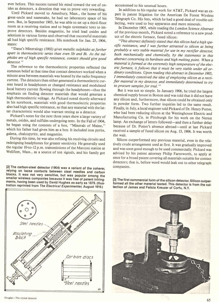
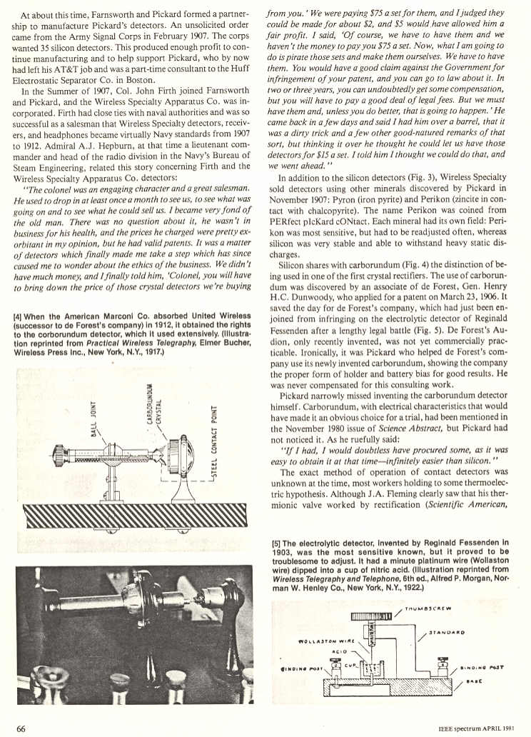
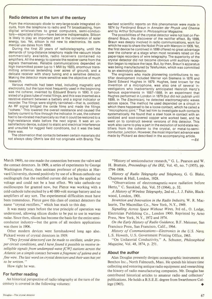
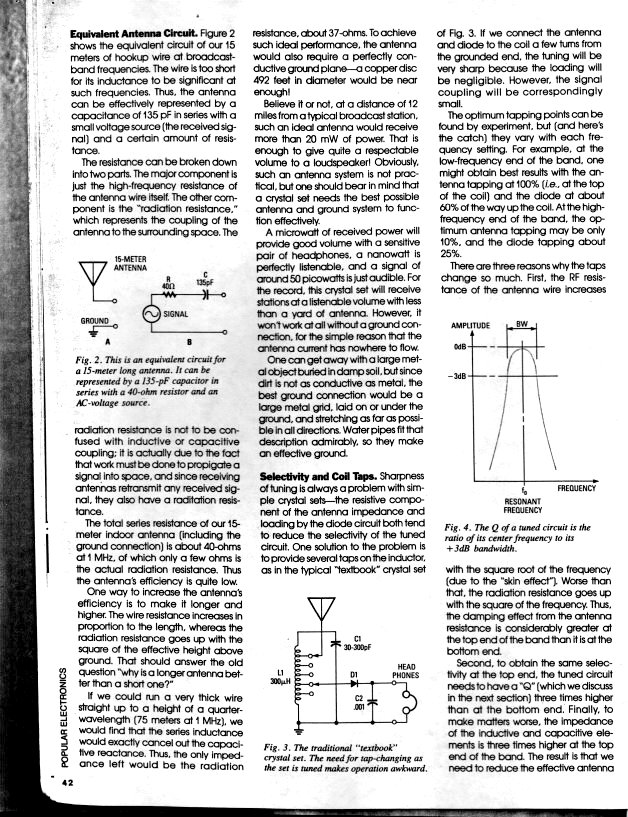
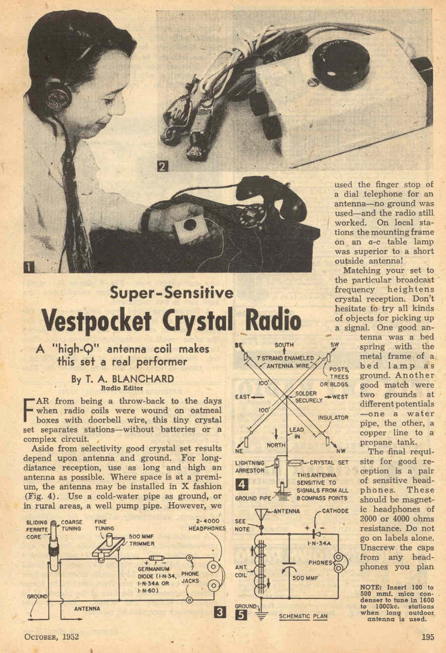
Further reading
[edit]- Ellery W. Stone (1919). Elements of Radiotelegraphy. D. Van Nostrand company. 267 pages.
- Elmer Eustice Bucher (1920). The Wireless Experimenter's Manual: Incorporating how to Conduct a Radio Club.
- Milton Blake Sleeper (1922). Radio Hook-ups: A Reference and Record Book of Circuits Used for Connecting Wireless Instruments. The Norman W. Henley publishing co.; 67 pages.
- JL Preston and HA Wheeler (1922) "Construction and operation of a simple homemade radio receiving outfit", Bureau of Standards, C-120: Apr. 24, 1922.
- PA Kinzie (1996). Crystal Radio: History, Fundamentals, and Design. Xtal Set Society.
- Thomas H. Lee (2004). The Design of CMOS Radio-Frequency Integrated Circuits
- Derek K. Shaeffer and Thomas H. Lee (1999). The Design and Implementation of Low-Power CMOS Radio Receivers
- Ian L. Sanders. Tickling the Crystal – Domestic British Crystal Sets of the 1920s; Volumes 1–5. BVWS Books (2000–2010).
External links
[edit]- A website with lots of information on early radio and crystal sets
- Hobbydyne Crystal Radios History and Technical Information on Crystal Radios
- Ben Tongue's Technical Talk Section 1 links to "Crystal Radio Set Systems: Design, Measurements and Improvement".
- "Semiconductor archeology or tribute to unknown precursors[usurped]". earthlink.net/~lenyr.
- Nyle Steiner K7NS, Zinc Negative Resistance RF Amplifier for Crystal Sets and Regenerative Receivers Uses No Tubes or Transistors. November 20, 2002.
- Crystal Set DX? Roger Lapthorn G3XBM
- Details of crystals used in crystal sets
- Asquin, Don; Rabjohn, Gord (April 2012). "High Performance Crystal Radios" (PDF). Ottawa Electronics Club. Retrieved 2016-09-27.
- http://www.crystal-radio.eu/endiodes.htm Diodes
- http://www.crystal-radio.eu/engev.htm How to build a sensitive crystal receiver?
- http://uv201.com/Radio_Pages/Pre-1921/crystal_detectors.htm Crystal Detectors
- http://www.sparkmuseum.com/DETECTOR.HTM Radio Detectors
- The Crystal Set Perfected